| Admissions | Accreditation | Booksellers | Catalog | Colleges | Contact Us | Continents/States/Districts | Contracts | Distance Education | Emergency | Examinations | Forms | Grants | Hostels | Honorary Doctorate degree | Investment | Instructors | Lecture | Librarians | Membership | Professional Examinations | Programs | Progress Report | Recommendations | Research Grants | Researchers | Students login | School | Search | Seminar | Study Center/Centre | Sponsorship | Tutoring | Thesis | Universities | Work counseling |
|
Aircraft Structure What will the aircraft look like? What materials will you utilize for each part of the aircraft? How will you test each part of the aircraft for its ability to stand the load? How many workers are required to build this aircraft? Existing workers at the airports. Part of your time you need to focus on manufacture of aircraft. What are the specifications of the aircraft? What are the types of fuselage structure of an aircraft? Truss type fuselage structure Semimonocoque type fuselage structure What should be the diameter of the fuselage of the aircraft? What should be the length of the fuselage of the aircraft? What parameters are required to calculate the diameter and length of the fuselage of an aircraft? How is Reynolds number useful in construction of an aircraft? What are the types of wing structures of an aircraft? What are the various wing configurations of an aircraft? How will you test the structure for tension, compression, bending, shear, and torsion? If you need to manufacture an aircraft with maximum takeoff weight of 640 tons, cruising altitude 30,000 feet, Cruise speed of 800 km/h (430 knots, 500 mph), range with maximum fuel of 15,400 km (9,570 mi), how will you go ahead? How will you calculate the total miles from Chicago, Illinois, in North America to Srinagar, Kashmir, in Asia and specifications of nonstop flight required? How do you determine empty weight of an aircraft? How do you determine maximum takeoff weight of an aircraft? At one time, aircraft used to be weighted while mounting on a load cell. Nowadays there is built-in electronic weighing for aircraft. The load cells are built into the axles of the landing gear. How do you determine the specific weight at which an aircraft will balance in cruise control at 30,000 feet altitude? If an aircraft manufacturer displays maximum aircraft takeoff weight of 450 tons, how did the manufacturer calculate this figure? If the maximum takeoff weight of the aircraft is 450 tons, what should be the empty weight of the aircraft? Aircraft Inspections What should you know about aircraft inspections? What questions should be answered in an aircraft inspection? Who should do an aircraft inspection? What should be included in a Standard Airworthiness Certificate of an aircraft? Criminal activity involving aircraft operations. What are reported criminal activities involving aircraft operations? |
| Fuselage |
| The design of the fuselage is based on payload requirements, aerodynamics, and structures. The overall dimensions of the fuselage affect the drag through several factors. Fuselages with smaller fineness ratios have less wetted area to enclose a given volume, but more wetted area when the diameter and length of the cabin are fixed. The higher Reynolds number and increased tail length generally lead to improved aerodynamics for long, thin fuselages, at the expense of structural weight. Selection of the best layout requires a detailed study of these trade-offs, but to start the design process, something must be chosen. This is generally done by selecting a value not too different from existing aircraft with similar requirements, for which such a detailed study has presumably been done. In the absence of such guidance, one selects an initial layout that satisfies the payload requirements. The following sections are divided into several parts: the selection of cabin cross-section dimensions, determination of fuselage length and shape, FAR's related to fuselage design and seating, and finally considerations related to supersonic aircraft. |
|
Aircraft Structure - An introduction to major airplane components
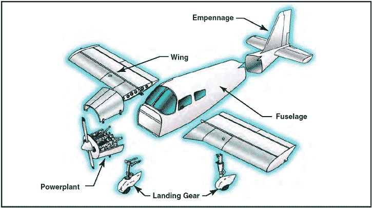
According to the current Title 14 of the Code of __________, Definitions and Abbreviations, an aircraft is a device that is used, or intended to be used, for flight. Categories of aircraft for certification of airmen include airplane, rotorcraft, lighter-than-air, powered-lift, and glider. Part 1 also defines airplane as an engine-driven, fixed-wing aircraft heavier than air that is supported in flight by the dynamic reaction of air against its wings. This webpage provides a brief introduction to the airplane and its major components. Major components Although airplanes are designed for a variety of purposes, most of them have the same major components. The overall characteristics are largely determined by the original design objectives. Most airplane structures include a fuselage, wings, an empennage, landing gear, and a powerplant.
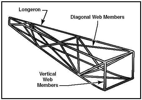
Figure 1: Airplane components. Fuselage The fuselage includes the cabin and/or cockpit, which contains seats for the occupants and the controls for the airplane. In addition, the fuselage may also provide room for cargo and attachment points for the other major airplane components. Some aircraft utilize an open truss structure. The truss-type fuselage is constructed of steel or aluminum tubing. Strength and rigidity is achieved by welding the tubing together into a series of triangular shapes, called trusses.
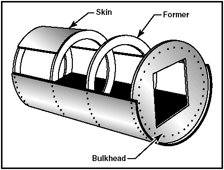
Figure 2: The Warren truss. Construction of the Warren truss features longerons, as well as diagonal and vertical web members. To reduce weight, small airplanes generally utilize aluminum alloy tubing, which may be riveted or bolted into one piece with cross-bracing members. As technology progressed, aircraft designers began to enclose the truss members to streamline the airplane and improve performance. This was originally accomplished with cloth fabric, which eventually gave way to lightweight metals such as aluminum. In some cases, the outside skin can support all or a major portion of the flight loads. Most modern aircraft use a form of this stressed skin structure known as monocoque or semimonocoque construction. The monocoque design uses stressed skin to support almost all imposed loads. This structure can be very strong but cannot tolerate dents or deformation of the surface. This characteristic is easily demonstrated by a thin aluminum beverage can. You can exert considerable force to the ends of the can without causing any damage. However, if the side of the can is dented only slightly, the can will collapse easily. The true monocoque construction mainly consists of the skin, formers, and bulkheads. The formers and bulkheads provide shape for the fuselage.
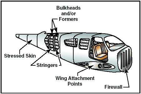
Figure 3: Monocoque fuselage design. Since no bracing members are present, the skin must be strong enough to keep the fuselage rigid. Thus, a significant problem involved in monocoque construction is maintaining enough strength while keeping the weight within allowable limits. Due to the limitations of the monocoque design, a semi-monocoque structure is used on many of today´s aircraft. The semi-monocoque system uses a substructure to which the airplane´s skin is attached. The substructure, which consists of bulkheads and/or formers of various sizes and stringers, reinforces the stressed skin by taking some of the bending stress from the fuselage.
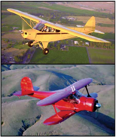
Figure 4: Semi-monocoque construction. The main section of the fuselage also includes wing attachment points and a firewall. On single-engine airplanes, the engine is usually attached to the front of the fuselage. There is a fireproof partition between the rear of the engine and the cockpit or cabin to protect the pilot and passengers from accidental engine fires. This partition is called a firewall and is usually made of heat-resistant material such as stainless steel. Wings The wings are airfoils attached to each side of the fuselage and are the main lifting surfaces that support the airplane in flight. There are numerous wing designs, sizes, and shapes used by the various manufacturers. Each fulfills a certain need with respect to the expected performance for the particular airplane. How the wing produces lift is explained in aerodynamics pages. Wings may be attached at the top, middle, or lower portion of the fuselage. These designs are referred to as high-, mid-, and low-wing, respectively. The number of wings can also vary. Airplanes with a single set of wings are referred to as monoplanes, while those with two sets are called biplanes.
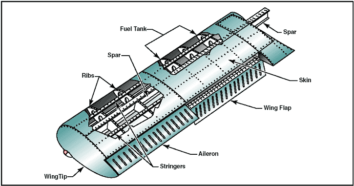
Figure 5: Monoplane and biplane. Many high-wing airplanes have external braces, or wing struts, which transmit the flight and landing loads through the struts to the main fuselage structure. Since the wing struts are usually attached approximately halfway out on the wing, this type of wing structure is called semi-cantilever. A few high-wing and most low-wing airplanes have a full cantilever wing designed to carry the loads without external struts. The principal structural parts of the wing are spars, ribs, and stringers.
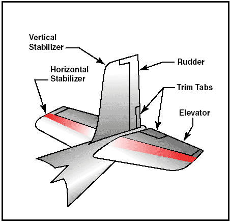
Figure 6: Wing components. These are reinforced by trusses, I-beams, tubing, or other devices, including the skin. The wing ribs determine the shape and thickness of the wing (airfoil). In most modern airplanes, the fuel tanks either are an integral part of the wing´s structure, or consist of flexible containers mounted inside of the wing. Attached to the rear, or trailing, edges of the wings are two types of control surfaces referred to as ailerons and flaps. Ailerons extend from about the midpoint of each wing outward toward the tip and move in opposite directions to create aerodynamic forces that cause the airplane to roll. Flaps extend outward from the fuselage to near the midpoint of each wing. The flaps are normally flush with the wing´s surface during cruising flight. When extended, the flaps move simultaneously downward to increase the lifting force of the wing for takeoffs and landings. Empennage The correct name for the tail section of an airplane is empennage. The empennage includes the entire tail group, consisting of fixed surfaces such as the vertical stabilizer and the horizontal stabilizer. The movable surfaces include the rudder, the elevator, and one or more trim tabs.
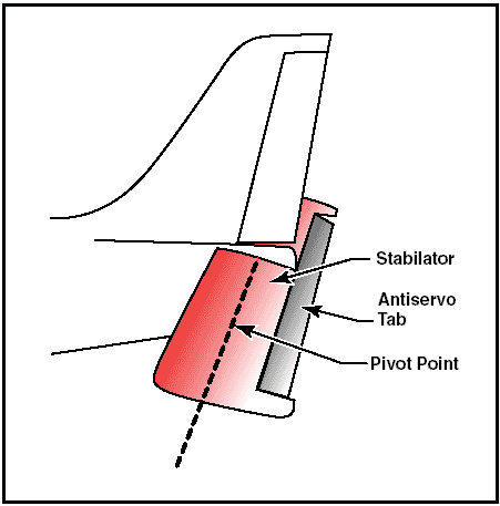
Figure 7: Empennage components. A second type of empennage design does not require an elevator. Instead, it incorporates a one-piece horizontal stabilizer that pivots from a central hinge point. This type of design is called a stabilator, and is moved using the control wheel, just as you would the elevator. For example, when you pull back on the control wheel, the stabilator pivots so the trailing edge moves up. This increases the aerodynamic tail load and causes the nose of the airplane to move up. Stabilators have an antiservo tab extending across their trailing edge.
Figure 8: Stabilator components. The antiservo tab moves in the same direction as the trailing edge of the stabilator. The antiservo tab also functions as a trim tab to relieve control pressures and helps maintain the stabilator in the desired position. The rudder is attached to the back of the vertical stabilizer. During flight, it is used to move the airplane´s nose left and right. The rudder is used in combination with the ailerons for turns during flight. The elevator, which is attached to the back of the horizontal stabilizer, is used to move the nose of the airplane up and down during flight. Trim tabs are small, movable portions of the trailing edge of the control surface. These movable trim tabs, which are controlled from the cockpit, reduce control pressures. Trim tabs may be installed on the ailerons, the rudder, and/or the elevator. Landing gear The landing gear is the principle support of the airplane when parked, taxiing, taking off, or when landing. The most common type of landing gear consists of wheels, but airplanes can also be equipped with floats for water operations, or skis for landing on snow.
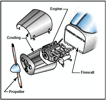
Figure 9: Landing gear. The landing gear consists of three wheels — two main wheels and a third wheel positioned either at the front or rear of the airplane. Landing gear employing a rearmounted wheel is called conventional landing gear. Airplanes with conventional landing gear are sometimes referred to as tailwheel airplanes. When the third wheel is located on the nose, it is called a nosewheel, and the design is referred to as a tricycle gear. A steerable nosewheel or tailwheel permits the airplane to be controlled throughout all operations while on the ground. The powerplant The powerplant usually includes both the engine and the propeller. The primary function of the engine is to provide the power to turn the propeller. It also generates electrical power, provides a vacuum source for some flight instruments, and in most single-engine airplanes, provides a source of heat for the pilot and passengers. The engine is covered by a cowling, or in the case of some airplanes, surrounded by a nacelle. The purpose of the cowling or nacelle is to streamline the flow of air around the engine and to help cool the engine by ducting air around the cylinders. The propeller, mounted on the front of the engine, translates the rotating force of the engine into a forwardacting force called thrust that helps move the airplane through the air.
Figure 10: Engine compartment. What does a pilot need to know about the airplane? The Basics of Flying What Are The Different Parts Of An Airplane? Airplanes come in many shapes and sizes, but they all have similar parts. Look at this picture to see what they are!  The body of the airplane is called the fuselage. This includes the cockpit, where the pilot sits during the flight. Airplanes have wings to lift them up into the sky. On the rear side of each wing is a part that moves up and down called an aileron. Ailerons help the airplane turn right or left. Flaps help the airplane fly slowly for landing. The tail that sticks straight up like a shark's fin has a part called the rudder. The rudder helps turn the nose of the airplane right or left. The flat part of the tail has a part called the elevator. The elevator makes the airplane's nose move up or down. Since the wings on an airplane don't move up and down like a bird's wings do, something has to make the airplane go forward. That's where the engine and the propeller come in. The engine turns the propeller and the propeller pulls (or in some cases pushes) the airplane through the sky! A Typical Airplane Cockpit 
The pilot sits inside the airplane in what is known as the cockpit. There are many instruments and switches to operate things like radios so that the pilot can talk to the tower. The pilot controls the airplane by using either a control wheel or a control stick. These controls let the pilot move the elevators on the tail and the ailerons on the wings, which in turn move the airplane. The elevators move by pulling back and pushing forward on these controls. When the pilot moves the controls to the right or to the left, the ailerons on the wings move up or down. On the floor of the cockpit are pedals that operate the brakes and rudder. When the pilot pushes the right pedal, the rudder turns to the right. It will turn left when the left pedal is pushed.  click photo to see a real cockpit in a plane that you might get to fly! This is the cockpit of the Cessna 172 typically flown by our Flight Leader, Steve Taylor. For fun, you can learn about the common instruments & radios in a typical aircraft cockpit at the Cyber-Cockpit website The Four Basic Forces of Flight  There are four forces that affect an airplane in flight: Lift, Gravity, Thrust and Drag. GRAVITY is the force that keeps all objects on earth. If we pick up a ball and let it go, it will drop quickly to the ground because of gravity. LIFT is a force that an airplane must create to overcome the force of gravity. An airplane does this by making lift with its wings as the airplane moves forward. An airplane's forward movement is produced by THRUST. Thrust is created by the engine and the rotating propeller. Just as lift overcomes the force of gravity during flight, thrust must overcome the force known as DRAG, which resists movement of an object — in this case, our airplane! Large Aircraft Components Diagrams: Radome, Nose landing gear doors, Wing to body fairing, Cowl components, Pylon fairings, Carbon wheel brakes, Fixed leading edge and, trailing edge panels, Outboard and inboard spoilers, Outbord and inboard flaps, Flap fairings, Ailerons, Main landing gear doors and fairings, Furnishing and floor panels, Tailplane, Elevators, Rudder, Fin. 
Airbus Airplane Wing Structure and Terminology Airbus Airplane Wing Structure and Terminology: Stringers, Underside of Skin Panel, Ribs, Front Spar, Center Spar, Rear Spar, Typical Rib, Skin Panel. |
  Truss-type fuselage structure.  Seminonocoque and monocoque fuselage structure.  http://adg.stanford.edu/aa241/AircraftDesign.html |

