
A substation is a high-voltage electric system facility. It is used to switch generators, equipment, and circuits or lines in and out of a system. It also is used to change AC voltages from one level to another, and/or change alternating current to direct current or direct current to alternating current. Some substations are small with little more than a transformer and associated switches. Others are very large with several transformers and dozens of switches and other equipment. There are three aspects to substations: 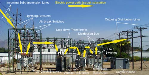 Figure 1. Typical substation o Substation Types o Substation Functions o Substation Equipment * Substation Types: Although, there are generally four types of substations there are substations that are a combination of two or more types. o Step-up Transmission Substation o Step-down Transmission Substation o Distribution Substation o Underground Distribution Substation Step-up Transmission Substation A step-up transmission substation receives electric power from a nearby generating facility and uses a large power transformer to increase the voltage for transmission to distant locations. A transmission bus is used to distribute electric power to one or more transmission lines. There can also be a tap on the incoming power feed from the generation plant to provide electric power to operate equipment in the generation plant. A substation can have circuit breakers that are used to switch generation and transmission circuits in and out of service as needed or for emergencies requiring shut-down of power to a circuit or redirection of power. The specific voltages leaving a step-up transmission substation are determined by the customer needs of the utility supplying power and to the requirements of any connections to regional grids. Typical voltages are: High voltage (HV) ac: 69 kV, 115 kV, 138 kV, 161 kV, 230 kV Extra-high voltage (EHV) ac: 345 kV, 500 kV, 765 kV Ultra-high voltage (UHV) ac: 1100 kV, 1500 kV Direct-current high voltage (dc HV): ±250 kV, ±400 kV, ±500 kV Direct current voltage is either positive or negative polarity. A DC line has two conductors, so one would be positive and the other negative.  Figure 2. Step-up AC transmission substation Figure 3. Step-up transmission substation to AC transmission lines Step-down Transmission Substation Step-down transmission substations are located at switching points in an electrical grid. They connect different parts of a grid and are a source for subtransmission lines or distribution lines. The step-down substation can change the transmission voltage to a subtransmission voltage, usually 69 kV. The subtransmission voltage lines can then serve as a source to distribution substations. Sometimes, power is tapped from the subtransmission line for use in an industrial facility along the way. Otherwise, the power goes to a distribution substation. 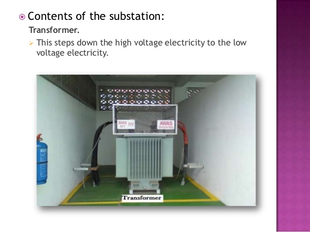 Figure 4. Step-down transmission substation Figure 5. Step-down power transformer Distribution Substation Distribution substations are located near to the end-users. Distribution substation transformers change the transmission or subtransmission voltage to lower levels for use by end-users. Typical distribution voltages vary from 34,500Y/19,920 volts to 4,160Y/2400 volts. 34,500Y/19,920 volts is interpreted as a three-phase circuit with a grounded neutral source. This would have three high-voltage conductors or wires and one grounded neutral conductor, a total of four wires. The voltage between the three phase conductors or wires would be 34,500 volts and the voltage between one phase conductor and the neutral ground would be 19,920 volts. From here the power is distributed to industrial, commercial, and residential customers. 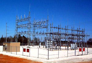 Figure 6. Distribution substation distribution_substation_sm2.jpg" width="500" height="325" alt="" border="0" align=""> Figure 7. Distribution substation 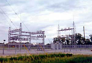 Figure 8. Distribution substation 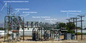 Figure 9. Distribution substation |
|
Underground Distribution Substation Underground distribution substations are also located near to the end-users. Distribution substation transformers change the subtransmission voltage to lower levels for use by end-users. Typical distribution voltages vary from 34,500Y/19,920 volts to 4,160Y/2400 volts. An underground system may consist of these parts:  Figure 10. Underground Distribution Substation * Conduits * Duct Runs * Manholes * High-Voltage Underground Cables * Transformer Vault * Riser * Transformers From here the power is distributed to industrial, commercial, and residential customers. |
|
Substation Functions Substations are designed to accomplish the following functions, although not all substations have all these functions: * Change voltage from one level to another * Regulate voltage to compensate for system voltage changes * Switch transmission and distribution circuits into and out of the grid system * Measure electric power qualities flowing in the circuits * Connect communication signals to the circuits * Eliminate lightning and other electrical surges from the system * Connect electric generation plants to the system * Make interconnections between the electric systems of more than one utility * Control reactive kilovolt-amperes supplied to and the flow of reactive kilovolt-amperes in the circuits |
| Electric Power Basics |
| Electric Power Glossary |
| Transformer |
| Substation Operations Engineer |
|
||
| The major components of a typical substation are: | ||
|
Substation Equipment: Air Circuit Breakers Air Circuit Breakers Air circuit breakers are used to interrupt circuits while current flows through them. Compressed air is used to quench the arc when the connection is broken. 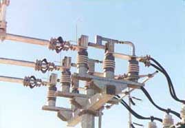 Figure 1. Air circuit breaker Substation Equipment: Batteries Batteries Batteries are used in the substation control house as a backup to power the control systems in case of a power blackout. 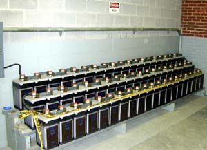 Figure 1. Backup batteries in the control house Substation Equipment: Bus Support Insulators Bus Support Insulators Bus support insulators are porcelain or fiberglass insulators that serve to isolate the bus bar switches and other support structures and to prevent leakage current from flowing through the structure or to ground. These insulators are similar in function to other insulators used in substations and transmission poles and towers. 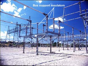 Figure 1. Bus support insulators Substation Equipment: Capacitor Bank Capacitor Bank Capacitors are used to control the level of the voltage supplied to the customer by reducing or eliminating the voltage drop in the system caused by inductive reactive loads.  Figure 1. Capacitor bank, end view  Figure 2. Capacitor bank, side view Substation Equipment: Circuit Switchers Circuit Switchers Circuit switchers provide equipment protection for transformers, lines, cables, and capacitor banks. They also are used to energize and deenergize capacitor banks and other circuits.  Figure 1. Circuit switchers 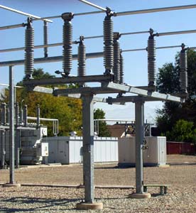 Figure 2. Circuit switcher Substation Equipment: Concrete Foundations Concrete Foundations Concrete foundations or pads are laid for all large equipment, support structures, and control buildings in a substation. 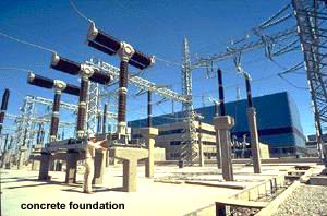 Figure 1. Concrete foundation - step-up transmission substation 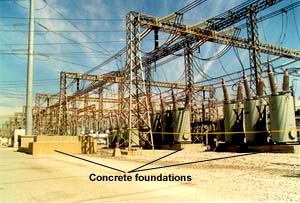 Figure 2. Concrete foundations Substation Equipment: Conduits Conduits Conduits are hollow tubes running from manhole to manhole in an underground transmission or distribution system. They can contain one or more ducts (See Duct Runs). They can be made of plastic (PVC), fiberglass, fiber, tile, concrete, or steel. PVC and fiberglass are most commonly used. 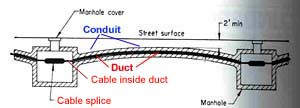 Figure 1. Conduit Substation Equipment: Control House Control House The substation control house contains switchboard panels, batteries, battery chargers, supervisory control, power-line carrier, meters, and relays. The control house provides all weather protection and security for the control equipment. It is also called a doghouse. 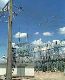 Figure 1. Control house 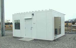 Figure 2. Substation control house 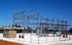 Figure 3. Control house Substation Equipment: Control Panels Control Panels Control panels contain meters, control switches and recorders located in the control building, also called a doghouse. These are used to control the substation equipment, to send power from one circuit to another or to open or to to shut down circuits when needed. 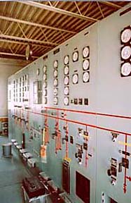 Figure 1. Substation control panel 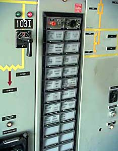 Figure 2. Substation control panel, detail Substation Equipment: Control Wires Control Wires Control wires are installed connecting the control house control panels to all the equipment in the substation. A typical substation control house contains several thousand feet of conduit and miles of control wire. 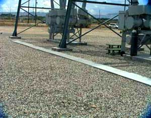 Figure 1. Control wire conduit 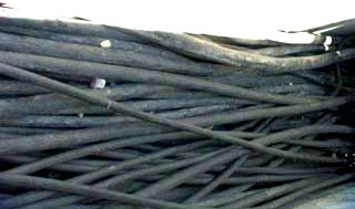 Figure 2. Control wires  Figure 3. Control wire conduit leading into control house Substation Equipment: Converter Stations Converter Stations Converter stations are located at the terminals of a DC transmission line. Converter stations can change alternating current into direct current or change direct current to alternating current. Sometimes converter stations are located at a generation power plant or at transmission substations. Two unsynchronized AC transmission systems can be connected together with converter stations. Converter stations are also found in most substations for converting the emergency battery back-up system to AC power for use in an emergency. 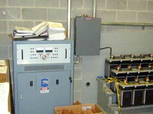 Figure 1. Converter station in battery room Substation Equipment: Coupling Capacitors Coupling Capacitors Coupling capacitors are used to transmit communication signals to transmission lines. Some are used to measure the voltage in transmission lines. In signal transmission the coupling capacitor is part of a power line carrier circuit as shown in the schematic below. A coupling capacitor is used in this circuit in conjunction with a line trap. Line traps can be installed at the substation or on a transmission line tower. 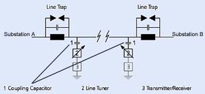 Figure 1. Power line carrier schematic showing use of coupling capacitors 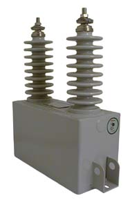 Figure 2. Primary coupling capacitor 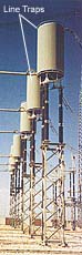 Figure 3. Substation line traps Substation Equipment: Current Transformers Current Transformers Current transformers can be used to supply information for measuring power flows and the electrical inputs for the operation of protective relays associated with the transmission and distribution circuits or for power transformers. These current transformers have the primary winding connected in series with the conductor carrying the current to be measured or controlled. The secondary winding is thus insulated from the high voltage and can then be connected to low-voltage metering circuits. Current transformers are also used for street lighting circuits. Street lighting requires a constant current to prevent flickering lights and a current transformer is used to provide that constant current. In this case the current transformer utilizes a moving secondary coil to vary the output so that a constant current is obtained. Figure 1. Metering current transformers Figure 2. Pole type constant current transformer Figure 3. 400 kV current transformer Substation Equipment: Disconnect Switches Disconnect Switches Disconnect switches or circuit breakers are used to isolate equipment or to redirect current in a substation. Many different types of disconnect switches are shown below. 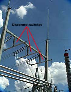 Figure 1. Disconnect switches on an outgoing distribution circuit 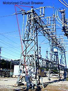 Figure 2. Motorized disconnect switch (circuit breaker) 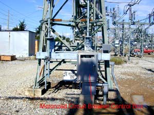 Figure 3. Motorized circuit breaker - control box 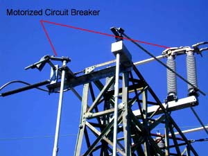 Figure 4. Motorized circuit breaker - switch detail 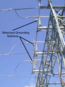 Figure 5. Substation motorized grounding switches Substation Equipment: Distribution Bus Distribution Bus A distribution bus is a steel structure array of switches used to route power out of a substation. 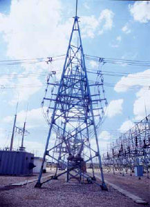 Figure 1. Distribution bus 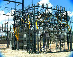 Figure 2. Distribution bus Substation Equipment: Duct Runs Duct Runs Duct runs are hollow tubes running from manhole to manhole inside a conduit (see conduits) in an underground system. They are of various sizes usually from 2 to 6 inches in diameter. Electrical cables are run through ducts and the ducts are sized accordingly. The diameter of a duct should be at least 1/2 to 3/4 inch greater than the diameter of the cable(s) installed in the duct. They can be made of plastic (PVC), fiberglass, fiber, tile, concrete, or steel. PVC and fiberglass are most commonly used. Figure 1. Duct run within conduit showing drainage in both directions Figure 2. Duct run on a grade  Figure 2. Conduit on a grade Substation Equipment: Frequency Changers Frequency Changers A frequency changer is a motor-generator set that changes power of an alternating current system from one frequency to one or more different frequencies, with or without a change in the number of phases, or in voltage. Sometimes a converter is used to accomplish this. 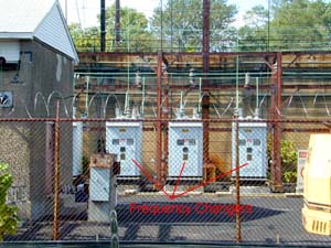 Figure 1. Frequency changers at a transportation substation Substation Equipment: Grounding Resistors Grounding Resistors Grounding Resistors are designed to provide added safety to industrial distribution systems by limiting ground fault current to reasonable levels. They are usually connected between earth ground and the neutral of power transformers, power generators or artificial neutral transformers. Their main purpose is to limit the maximum fault current to a value which will not damage generating, distribution or other associated equipment in the power system, yet allow sufficient flow of fault current to operate protective relays to clear the fault. 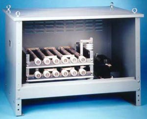 Figure 1. Grounding resistor Substation Equipment: Grounding Transformers Grounding Transformers A grounding transformer is intended primarily to provide a neutral point for grounding purposes. It may be provided with a delta winding in which resistors or reactors are connected. Figure 1. Grounding transformer - front view Figure 2. Grounding transformer - back view Substation Equipment: High-Voltage Underground Cables High-Voltage Underground Cables High-Voltage underground cables are constructed in many different ways, but are usually shielded cables. They are made with a conductor, conductor-strand shielding, insulation, semi-conducting insulation shielding, metallic insulation shielding, and a sheath. The sheath can be metallic and may then serve as the metallic insulation shielding and be covered with a nonmetallic jacket to protect the sheath. This sheath helps to reduce or eliminate inductive reactance. Such cables are commonly used in circuits operating at 2400 volts or higher.  Figure 1. High-voltage underground cables 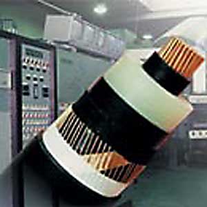 Figure 2. High-voltage underground cables Substation Equipment: High Voltage Fuses High Voltage Fuses High voltage fuses are used to protect the electrical system in a substation from power transformer faults. They are switched for maintenance and safety. 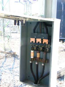 Figure 1. High voltage fuses in a switch box 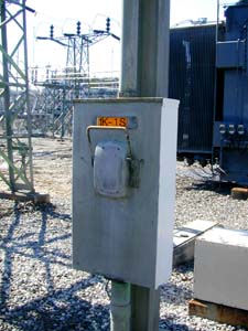 Figure 2. External switch for high voltage fuses | ||
|
Substation Equipment: Lightning Arresters
Lightning arresters are protective devices for limiting surge voltages due to lightning strikes or equipment faults or other events, to prevent damage to equipment and disruption of service. Also called surge arresters. Lightning arresters are installed on many different pieces of equipment such as power poles and towers, power transformers, circuit breakers, bus structures, and steel superstructures in substations. 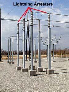 Figure 1. Lightning arresters on bus structures  Figure 2. Lightning arrester on distribution pole transformer 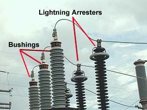 Figure 3. Lightning arresters Figure 4. Lightning arrester on substation power transformer Substation Equipment: Manholes Manholes A manhole is the opening in the underground duct system which houses cables splices and which cablemen enter to pull in cable and to make splices and tests. Also called a splicing chamber or cable vault.
Figure 1. Manholes 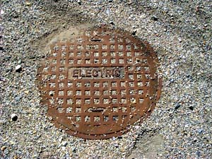
Figure 2. Manhole cover Substation Equipment: Metal-clad Switchgear Metal-clad Switchgear Switchgear can be either for outdoor use or indoor use. An outdoor metal-clad switchgear is a weatherproof housing for circuit breakers, protective relays, meters, current transformers, potential transformers, bus conductors, and other equipment. An indoor switchgear must be protected from the environment and contains the same types of equipment as the outdoor type. 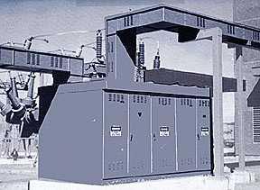
Figure 1. Outdoor metal-clad switchgear 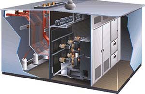
Figure 2. Outdoor metal-clad switchgear - cut-a-way view 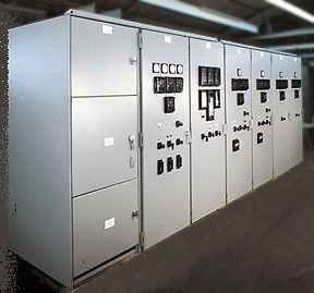
Figure 3. Indoor metal-clad switchgear Substation Equipment: Meters Meters Various types of meters are found in substation control houses. They all are measuring devices and can be an indicating meter or a recording meter. An indicating meter shows on a dial the quantity being measured. A recording meter makes a permanent record of the quantity being measured, usually by tracing a line on a chart or graph. Newer recording meters store the information electronically. The photo below left is an indicating amperage meter. On the right is a recording meter. 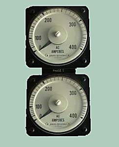
Figure 1. An indicating AC amperes meter 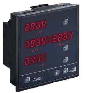
Figure 2. Recording power meter Substation Equipment: Microwave Microwave Substations commonly use microwave communication equipment for communication with local and regional electric power system control centers. This system allows for rapid communication and signaling for controlling the routing of power. Electric power for microwave transmission comes from special transformers that reduce incoming transmission voltage to that required for the microwave system. 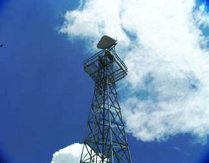
Figure 1. Substation microwave communication tower Figure 2. Microwave power transformers Substation Equipment: Oil Circuit Breakers Oil Circuit Breakers Oil circuit breakers are used to switch circuits and equipment in and out of a system in a substation. They are oil filled to provide cooling and to prevent arcing when the switch is activated. 
Figure 1. Oil circuit breakers in a 41 kV circuit 
Figure 2. Oil circuit breakers in a distribution circuit Substation Equipment: Potential Transformers Potential Transformers Potential transformers are required to provide accurate voltages for meters used for billing industrial customers or utility companies. Figure 1. Potential transformers Figure 2. Potential transformer Substation Equipment: Potheads Potheads A type of insulator with a bell or pot-like shape used to connect underground electrical cables to overhead lines. It serves to separate the bunched-up conductors from one another in the cable to the much wider separation in the overhead line. It also seals the cable end from the weather. Potheads are mounted on a distribution pole and the assembly is called a riser pole. 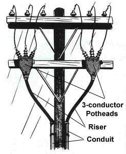 Figure 1. Three conductor potheads on pole 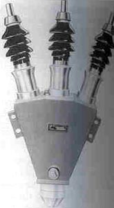 Figure 2. Three conductor pothea 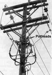 Figure 3. Potheads on pole Figure 3. Potheads on pole Substation Equipment: Power-line Carrier Power-line Carrier A power line carrier is communication equipment that operates at radio-frequencies, generally below 600 kilohertz, to transmit information over electric power transmission lines. A high frequency signal is superimposed on the normal voltage on a power circuit. The power line carrier is usually coupled to the power line by means of a coupling capacitor in conjunction with a line trap. A device for producing radio-frequency power for transmission on power lines. Figure 1. Power-line carrier schematic 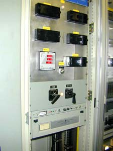 Figure 2. Power-line carrier device in control house Substation Equipment: Power Transformers Power Transformers Power transformers raise or lower the voltage as needed to serve the transmission or distribution circuits. Figure 1. Power transformer, back view Figure 2. Large power transformers Figure 3. Power Transformer, front view Figure 4. Step-up transformer diagram Substation Equipment: Rectifiers Rectifiers A rectifier is a device used to convert alternating current to direct current.  Figure 1. Full wave rectifier circuit diagram 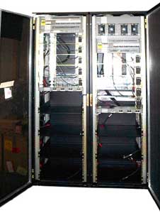 Figure 2. Rectifier Substation Equipment: Relays Relays A relay is a low-powered device used to activate a high-powered device. Relays are used to trigger circuit breakers and other switches in substations and transmission and distribution systems. 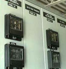 Figure 1. Substation control panel relays 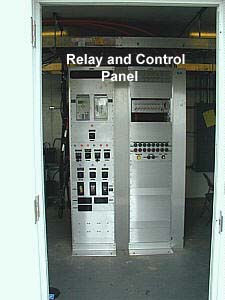
Figure 2. Relay and control panel Substation Equipment: SF6 Circuit Breakers SF6 Circuit Breakers SF6 circuit breakers operate to switch electric circuits and equipment in and out of the system. These circuit breakers are filled with compressed sulfur-hexafluoride gas which acts to open and close the switch contacts. The gas also interrupts the current flow when the contacts are open. 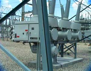 Figure 1. SF6 gas power circuit breaker 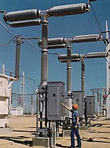 Figure 2. SF6 gas power circuit breaker Substation Equipment: Shunt Reactors Shunt Reactors Shunt reactors are used in an extra high-voltage substation to neutralize inductive reactance in long EHV transmission lines. The photo shows an installation of both an older version and a newer version of the reactor. 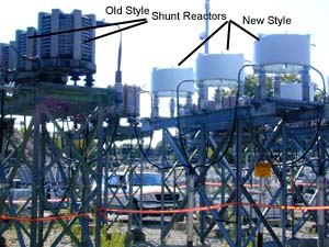 Figure 1. Shunt reactors in a substation Substation Equipment: Steel Superstructures Steel Superstructures Steel superstructures are used to support equipment, lines, and switches in substations as well as transmission and distribution line towers and poles. 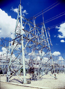
Figure 1. Steel superstructure for circuit breakers
Figure 2. Substation with many steel superstructures for equipment and connection supports Substation Equipment: Supervisory Control Supervisory Control Supervisory control refers to equipment that allows for remote control of a substation's functions from a system control center or other point of control. Supervisory control can be used to: * operate circuit breakers, * operate tap changers on power transformers, * supervise the position and condition of equipment, and * telemeter the quantity of energy in a circuit or in substation equipment. 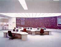 Figure 1. Supervisory control room 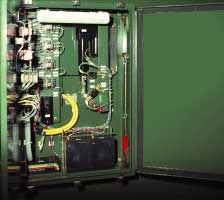 Figure 2. Supervisory control panel Substation Equipment: Suspension Insulators Suspension Insulators An insulator type usually made of porcelain that can be stacked in a string and hangs from a cross arm on a tower or pole and supports the line conductor. Suspension insulators are used for very high voltage systems when it is not practical or safe to use other types of insulators. They have an advantage in that one or more of the insulators in a string can be changed out without replacing the entire string. 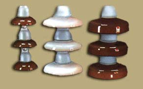 Figure 1. Suspension insulators 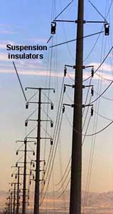 Figure 2. Suspension insulators 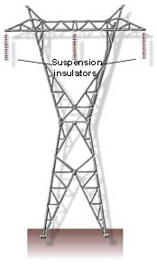 Figure 3. Suspension insulators Substation Equipment: Synchronous Condensers Synchronous Condensers A synchronous condenser is a synchronous machine running without mechanical load and supplying or absorbing reactive power to or from a power system. Also called a synchronous capacitor, synchronous compensator or rotating machinery. In November 1995, the first static synchronous compensator began operating at a TVA substation in Knoxville, Tennessee. This compensator can regulate voltage without expensive external capacitors or reactors. 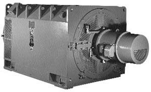
Figure 1. Synchronous condenser Substation Equipment: Transmission Bus Transmission Bus Transmission buses are steel structure arrays of switches used to route power into a substation. Figure 1. Transmission bus Figure 2. Transmission bus from inside Electric Power eTool Substation Equipment: Vacuum Circuit Breakers Vacuum Circuit Breakers A circuit breaker is a device used to complete, maintain, and interrupt currents flowing in a circuit under normal or faulted conditions. A vacuum circuit breaker utilizes a vacuum to extinguish arcing when the circuit breaker is opened and to act as a dielectric to insulate the contacts after the arc is interrupted. One type of circuit breaker is called a recloser. A vacuum recloser is designed to interrupt and reclose an AC current circuit automatically, and can be designed to cycle a set number of times before it must be reset manually. 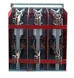 Figure 1. Vacuum circuit breaker, inside 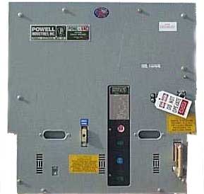 Figure 2. Vacuum circuit breaker, outside Operation of a Substation Electricity is generated in a thermal power plant, hydroelectric power plant, and nuclear power plant, etc. This electricity is then supplied to a transmission substation near the generating plant. In the transmission substation the voltage is increased substantially using step up transformers. The voltage is increased to reduce the transmission losses over long distances. This electricity then is supplied to a power substation where it is stepped down using step down transformers and then supplied to a distribution grid. In the distribution grid there are additional transformers and voltage is further reduced for distributing further down the grid. From here the electricity is supplied to step down transformers near residential quarters that step down the voltage to 110/220 Volts as per each __________ requirement. |